Monday, August 16, 2010

How to Design Industrial Automation Control Systems ?

In the development of the industrial world is so fast that the industry needed automated equipment that can be gained speed, quality and efficiency in production.

In designing industrial Automation systems equipment we have to learn, analyze and apply a few things. As for some of these include:

1.Sensor
Censorship is the first thing we have to learn many types of sensors used in the industrial world, among others: Proximity sensors, heat sensors, pressure sensors, speed sensors and others.

2. Activator
That kind of drive what will we use for example: mechanical gears, hydraulic or pneumatis, Industrial electric motors.

3. Electronic equipment industry
Electronic equipment that is commonly used as a component of the control equipment for industries such as: SCR, TRIAC, transistors, an optocoupler.

4. Motor Drive.
Ie equipment that drives the electric motor such as: Inverters, DC motor control, etc..

5. Control Equipment
Ie component / equipment used as part of industrial Automation control equipment such as contactors, relays, Timers, Counter, Solenoid, limit switches, push buttons,

6. PLC or programmable logic control.
Namely the control equipment used in industrial control equipment. PLC is a compact control devices have input terminals and output terminals. In PLC there is a program to regulate the movement of equipment in the output set by the input equipment. Such as: PLC OMRON, SIEMENS, MITSUBISHI, etc..

If we have mastered all these components is then we can assemble and create automated industrial controls.

Wednesday, August 11, 2010

Industrial Electric AC Induction Motor And How Do They Work?

Industrial Electric AC Induction Motor And How Do They Work?

Let's take a brief look at a drive application. In a simple application with a
fixed speed fan using a motor starter. You could replace the 3-phase motor starter with
Variable Frequency Drive (VFD) to operate the fan at variable speed. Since you can operate
the fan at any speed below its maximum, you can vary airflow by controlling the motor speed
instead of the air outlet damper.

You call the electric motor like that is AC motor and another motor drive is DC. A motor
drive controls the speed, torque, direction and resulting horsepower of a motor. A DC drive
typically controls a shunt wound DC motor, which has separate armature and field circuits.
AC drives control AC induction motors, and-like their DC counterparts-control speed, torque,
and horsepower.


To understand how a drive controls the motor, we will take a short review of AC induction motors. Fig. 1 shows the construction of an induction motor. The two basic parts of the motor, the rotor and stator, work through magnetic interaction. A motor contains pole pairs. These are iron pieces in the stator, wound in a specific pattern to provide a north to south magnetic
field

Figure 1. AC Induction Motor Construction
Rotor and Stator Operation
With one pole pair isolated in a motor, the rotor (shaft) rotates at a specific speed: the base speed. The number of poles and the frequency applied determine this speed .This formula includes an effect called "slip." Slip is the difference between the rotor speed and the rotating magnetic field in the stator. When a magnetic field passes through
the conductors of the rotor, the rotor takes on magnetic fields of its own. These rotor magnetic fields will try to catch up to the rotating fields of the stator. However, it never does -- this difference is slip. Think of slip as the distance between
the greyhounds and the hare they are chasing around the track. As long as they don't catch up to the hare, they will continue to revolve around the track. Slip is what allows a motor to turn.

We can conveniently adjust the speed of a motor by changing the frequency applied to the motor. You could adjust motor speed by adjusting the number of poles, but this is a physical change to the motor. It would require rewinding, and result in a step change to the speed. So, for convenience, cost-efficiency, and precision, we change the frequency.

We change this ratio to change motor torque. An induction motor connected to a 460V, 60 Hz source has a ratio of 7.67. As long as this ratio stays in proportion, the motor will develop rated torque. A drive provides many different frequency outputs. At any given frequency output of the drive, you get a new torque curve.

Tuesday, August 10, 2010

Industrial Electric AC motor

AC motor

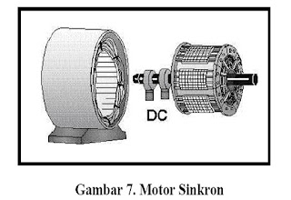
uses brushless electric currents to turn back on a regular basis over a period of time. The electric motor has two basic elements of power: "stator" and "rotor" as shown in Figure 7 daalam. Stator is a component of static electricity. The rotor is rotating electrical components to operate the motor. The main advantage of AC motor DC motor is that speed AC motor more difficult to control. To overcome this drawback, AC motors can be equipped with variable frequency drives to improve speed and lower power control. induction motor industry is the most popular cycling because of the reliability and easy maintenance. AC motor induction is very cheap (half price or less than the price of a DC motor) and also gives a relationship between power and weight is very high (about twice the DC motor).

synchronous AC motor

synchronous AC motor

Synchronous motor synchronous motor is an AC motor operating at fixed speed at a specific frequency. These engines require the production of electricity in direct current (DC) and the first pair of low, suited to a synchronous motor from use with small loads such as air compressors, generators and changes frequency of the motor. Synchronous motor capable of improving the power factor of the system, so often used in systems using much power. Electrical Energy Equipment: Electric Motors This motor rotates at synchronous speed is given by the formula Ns = 120 F / P Where: f = frequency of delivery frequency P = number of poles


Industrial Automation Related Post :

1.Industrial Electric DC Motor Types
2.Industrial Electric DC motors
3.Industrial Electric Motor
4.Industrial Automation

Monday, August 9, 2010

Industrial Electric DC Motor Types

Industrial Electric DC Motor Types:
1. DC Motor Types separate resources:

Discrete Field and armature voltage.

Advantages of DC Motors
- DC motors provide an excellent speed control for acceleration and deceleration with the effective
- Simple and Strong torque control.
- Allows precise control of motor voltage, which is necessary to control speed and torque.
- DC motors perform better than AC
- DC Motor comfortable portable and very suitable for special applications, such as industrial equipment and machinery.

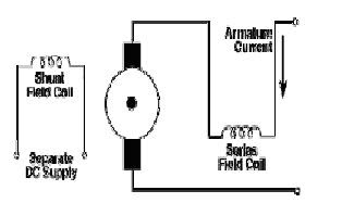
2. DC motor own resources / Self Excited: shunt motor
In the shunt motor, rolls Field / field (field shunt) connected in parallel with the armature coil / magneto (A)

Shunt DC Motor advantages:
- High torque at low speed
- High speed, and torque remain constant.


DC motor power alone: motor series

In a series motor, rolls Field / field (field shunt) connected in series with the armature coil / magneto (A) as shown in the picture. Therefore, the same as the current field current dynamo.
Following on the series motor speed (Rodwell International Corporation, 1997;
L.M. Photonics Ltd., 2002):
- The speed is limited to 5000 RPM
- Must avoid running series motor with no load will cause the motor
accelerate uncontrollably.
Series motors are suitable for use in the initial ignition requires torque
high, such as crane and hoist lifter

DC Motor Excellence series:
- Speed under Shunt DC Motor
- Torque initial height.

DC Motor Compound / Combined
DC compound motor is a combination of series and shunt motors. In the compound motor,
field winding (shunt field) are connected in parallel and in series with coil dynamo (A) as shown in figure 6. Thus, the motor torque ignition compound has a good beginning and a steady speed. The higher the percentage of incorporation (ie the percentage of field windings are connected in series), the higher the initial ignition of torque that can be handled by this motor.
Electric Motor DC Types2
Example:
- The merger of 40-50% makes this bike suitable for hoist and crane lifting equipment,

Permanent Magnet DC Motor
DC Motor DC Motor Shunt similar Fieldnya only using permanent magnets


DC Motor
Speed 3600 rpm
Voltage 200 VDC
Power 22 KW

Industrial Automation Related Post :

1.Industrial Electric DC Motor Types
2.Industrial Electric DC motors
3.Industrial Electric Motor
4.Industrial Automation

Sunday, August 8, 2010

Industrial Electric DC motors

Industrial Electric DC motors

Direct current motor, as the name implies, uses DC electricity flows. DC motors used on the specific use where
Starting the necessary high torque or acceleration of the equipment for a wide range of speeds.
Figure 3 shows a DC motor which has three main components: a

Industrial-Electric-DC-Motor
- Arctic terrain. In sederhada illustrated that the interaction of two magnetic poles will
cause the rotation of a DC motor. DC motor has a polar field
stationary and the moving dynamo bearing on the space between the polar magnetic field.
Simple DC motor has two field poles: a north pole and south pole. Line
magnetic energy increases across the openings between the poles from north to south.
For engines larger or more complex consists of one or more electromagnets.
Electromagnet to receive electricity from outside resources as a provider structure
field.
- Dinamo. If the inflow into the dynamo, then the flow will be an electromagnet.
A cylindrical dynamo, connected to the countershaft for driving
load. For the case of small DC motors, dynamos in rotating magnetic fields
formed by the poles, to the north and south magnetic poles changed its location. If
this happens, the current is turned to change the poles of north and south of the dynamo.
- Commutator. This component is mainly found in DC motors. Usefulness is
to reverse the direction of electric current in a dynamo. Commutator is also helpful in
transmission flows between the dynamo and resources.

The main advantages are as controller of DC motor speed, which is not
affect the quality of power supply. These motors can be controlled by regulating:
- Voltage dynamo - increases the voltage will increase the speed of dynamo
- Flow field - reducing the field current will increase the speed.

DC motors are available in many sizes, but its use is generally restricted
for multiple use of low-speed, low power consumption to moderate such as machine tools and rolling mills, because often there are problems with the electrical current direction of change in mechanical larger size. Also, the motor is restricted only for use in areas that are clean and not dangerous because the risk of sparks at the brush. DC motors are also relatively inexpensive compared to AC motors.
The relationship between speed, field flux and dynamo voltage shown in the following equation:
Electromagnetic force: E = KΦN
Torque: T = KΦIa

Where:
E = electromagnetic force developed at the dynamo terminals (volts)
Φ = flux field that is proportional to field current
N = speed in RPM (revolutions per minute)
T = electromagnetic torque
He = current dynamo
K = constant equation
The types of DC motors:
- DC motors separate power source / Separately Excited
If the field current is supplied from a separate source of DC motors it is called a separate power source /
separately excited.
- DC motors own resources / Self Excited: shunt motor
In the shunt motor, the field winding (shunt field) are connected in parallel with
dynamo coil (A) as shown in figure 4. Therefore the total current in the path represents the total flow and flow field dynamo.
- Constant speed in practice did not depend on the load (up to a certain torque
after its speed is reduced, see Figure 4) and therefore suitable for
commercial uses with low initial costs, such as machine tools.
- The speed can be controlled by placing prisoners in a series arrangement
by dynamo (reduced speed) or by putting detainees in the field current
(Velocity increases).

Industrial Automation Related Post :

1.Industrial Electric DC Motor Types
2.Industrial Electric DC motors
3.Industrial Electric Motor
4.Industrial Automation

Friday, August 6, 2010

Industrial Electric Motor

Industrial Electric Motor
As a driving force in the industry many people use electric motors

This section describes the main features of the electric motor.
1.1 Where is the motor used
Electric motor is an electromagnetic device that converts electrical energy
into mechanical energy. This mechanical energy is used to, for example, rotating impeller
pump, fan or blower, a compressor driving, lifting materials, etc.. Electric motor
used also in the home (mixer, electric drill, a fan of wind) and in industry. Electric motor
sometimes called the "work horse" because it is estimated that industrial motors
using about 70% of total electrical load in the industry.
2.1 How a motor works
The mechanism of action for all types of generally the same motor (Figure 1):
- An electric current in a magnetic field will exert a force
- If the current carrying wire is bent into a circle / loop, then
both sides of the loop, ie at right angles to the magnetic field, will get the force on
opposite direction.
- The pair produces a force play force / torque to rotate the coil.
- Motor-bike has a few loops on dinamonya to provide torque
more uniform and the composition of the magnetic field generated by electromagnetic
called the field coil.
In understanding a motor, it is important to understand what is meant by burden
motors. Refers to the output load power play / torque according to the speed
required. Expenses can generally be categorized into three groups (BEE India, 2004):
- Expenses are constant torque loads where requests vary the energy output
with a torque-speed operation but it does not vary. Example of an expense
constant torque is Conveyors, rotary kilns, and the constant displacement pump.
- Expenses with variable load torque is a torque which varies with
operating speed. Examples with variable torque loads are centrifugal pumps and
fan (torque varies as the square speed).
Electrical Energy Equipment: Electric Motors
Energy Efficiency Guide for Industry in Asia - www.energyefficiencyasia.org © UNEP 2
- Cost of energy is a constant torque load with the changing demand
and inversely proportional to velocity. Examples for the constant power load
is the machine tools.
Electric motor components varies for different types of motors, in chapter 2 is described for
each motor.


2. ELECTRIC MOTOR TYPES
This section describes the two main types of electric motors: DC and AC electric motors

Industrial Automation
Related Post :
1.Industrial Electric DC Motor Types
2.
Industrial Electric DC motors
3.Industrial Electric Motor
4.
INDUSTRIAL AUTOMATION CONTROL COMPONENTS
5.
Contactors / Relays
6.Industrial Automation

Previous Home