Industrial Electric AC Induction Motor And How Do They Work?
Let's take a brief look at a drive application. In a simple application with a
fixed speed fan using a motor starter. You could replace the 3-phase motor starter with
Variable Frequency Drive (VFD) to operate the fan at variable speed. Since you can operate
the fan at any speed below its maximum, you can vary airflow by controlling the motor speed
instead of the air outlet damper.
You call the electric motor like that is AC motor and another motor drive is DC. A motor
drive controls the speed, torque, direction and resulting horsepower of a motor. A DC drive
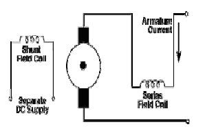
typically controls a shunt wound DC motor, which has separate armature and field circuits.
AC drives control AC induction motors, and-like their DC counterparts-control speed, torque,
and horsepower.

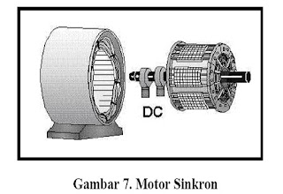
To understand how a drive controls the motor, we will take a short review of AC induction motors. Fig. 1 shows the construction of an induction motor. The two basic parts of the motor, the rotor and stator, work through magnetic interaction. A motor contains pole pairs. These are iron pieces in the stator, wound in a specific pattern to provide a north to south magnetic
field
Figure 1. AC Induction Motor Construction
Rotor and Stator Operation
With one pole pair isolated in a motor, the rotor (shaft) rotates at a specific speed: the base speed. The number of poles and the frequency applied determine this speed .This formula includes an effect called "slip." Slip is the difference between the rotor speed and the rotating magnetic field in the stator. When a magnetic field passes through
the conductors of the rotor, the rotor takes on magnetic fields of its own. These rotor magnetic fields will try to catch up to the rotating fields of the stator. However, it never does -- this difference is slip. Think of slip as the distance between
the greyhounds and the hare they are chasing around the track. As long as they don't catch up to the hare, they will continue to revolve around the track. Slip is what allows a motor to turn.
We can conveniently adjust the speed of a motor by changing the frequency applied to the motor. You could adjust motor speed by adjusting the number of poles, but this is a physical change to the motor. It would require rewinding, and result in a step change to the speed. So, for convenience, cost-efficiency, and precision, we change the frequency.
We change this ratio to change motor torque. An induction motor connected to a 460V, 60 Hz source has a ratio of 7.67. As long as this ratio stays in proportion, the motor will develop rated torque. A drive provides many different frequency outputs. At any given frequency output of the drive, you get a new torque curve.


